
I.Main Specifications
| Model | S-450 | S-600 | S-800 | S-900 | S-1100 | S-1200 |
| Rated centrifugal force | 390xg | 380xg | 370xg | 315xg | 315xg | 250xg |
| Required motor power (single) kW [hp] | 22 [30] | 30 [40] | 37 [50] | 75 [100] | 110 [150] | 150 [200] |
| Stroke length, approx. mm [in.] | 75 [3.0] | 75 [3.0] | 75 [3.0] | 85 [3.38] | 125 [5.0] | 140 [5.5] |
| Stroke frequency, approx. (adjustable) cycles/min | 30-40 | 30-40 | 30-40 | 30-44 | 30-40 | 30-36 |
| Basket diameter, mm [in.] | 457 [18] | 635 [25] | 812 [32] | 914 [36] | 1,118 [44] | 1,219 [48] |
| Basket length, mm [in.] | 508 [20] | 508 [20] | 508 [20] | 597 [23.5] | 724 [28.5] | 749 [29.5] |
| Transport weight, approx. (with motor) kg [lb] | 2,900 [6,400] | 3,600 [8,000] | 4,100 [9,000] | 7,900 [17,400] | 11,800 [26,000] | 17,600 [39,000] |
| L/D ratio | 1.111 | 0.800 | 0.625 | 0.653 | 0.648 | 0.615 |
II. Selection of Manufacturing Materials
A. Non-process-contact parts are made of carbon steel.
B. Process-contact parts:
• 316L stainless steel (international standard designation: S31603 or equivalent).
• Monel 400 nickel-copper alloy (international standard designation: NO4400 or equivalent).
• Carbon steel.
• Special metallurgy can be used according to process requirements.
• Special materials used by B&P for centrifuge manufacture include 25-6MO, Hastelloy, titanium, and others.
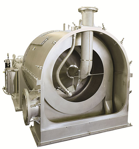
III. B&PIII. General Description of the B&P Pusher Centrifuge Dewatering System
The centrifuge separation system consists of the following major subassemblies or components:
A. Process housing
B. Basket
C. Integrated shaft assembly
D. Bearings
E. Pusher
F. Integrated hydraulic system
G. Drive
H. Base
Optional systems available at additional cost include:
I. Local control panel
J. Vibration isolation system
K. Screen backwash system
L. Airflow-controlled cyclone separator
M. Hydrocyclone slurry concentrator
N. Horizontal split process housing
O. CE-compliant design
A. Process housing
The standard process housing provides the structural process enclosure required to separate discharged solids and liquids, while also supporting piping such as slurry feed lines and wash liquor lines. Internal baffles in the liquid housing separate the mother liquor from the wash liquor. The main shaft passes through a backplate in the housing, where a liquid seal contains liquids and vapors generated during operation. The housing also provides multiple backwash connection options for cleaning the back side of the screen behind the basket hub.
The solid section of the housing is accessible through hinged doors that can be quickly opened and safely closed without moving any feed piping. A solids discharge ring, similar to a racetrack, surrounds and directs the discharged solids downward into the discharge chute. Multiple scrapers installed at the bottom of the basket allow solids to discharge tangentially along the surface of the discharge ring toward the collection chute. During operation, the solids can be observed through dual view windows integrated into the passageway.
B. Basket
The basket is centrifugally cast and features machined oval holes to drain feed liquor as required. B&P’s proprietary wedge-wire screen is mounted on the basket, and the single-stage screen cross-section is shown in “B”. The screen can also be reversed end-for-end to extend service life.
Note: The width of the wedge slots and the screen can be custom designed to meet specific user requirements.
C. Integrated shaft assembly
The integrated shaft assembly consists of a hollow shaft and a solid shaft with precision tapers. The hollow shaft matches the basket, while the solid shaft matches the pusher assembly plate. A hydraulically controlled piston is installed at the end of the solid shaft opposite the pusher plate. The servo mechanism serves as the drive for the pusher and is the main component of the pusher assembly. The pusher assembly is mounted on a Monel 400 nickel-copper alloy shaft sleeve, which also provides the running surface for four fixed lip seals designed to prevent contamination and wear. Scrapers prevent large contaminants from entering the sealing area, protecting both the lip seals and the shaft sleeve.
The standard shaft sleeve is designed to operate at temperatures up to 60°C (140°F). If the operating temperature exceeds this limit, the user must specify it in advance.
Dynamic balancing:The rotating system remains dynamically balanced at normal operating speed and meets or exceeds the following recognized international standards:
• ISO 1940 Grade G 6.3
• ANSI S2.19 Grade G6.3
• ASA STA 2 Grade G6.3
All equipment requires maintenance, including replacement of parts. B&P performs individual dynamic balance testing on every rotating component of the equipment system, so no additional balancing is required after assembly or replacement of rotating parts.
D. Bearings
The rotating system is supported by two sets of widely spaced, wear-resistant bearings, with the basket and screen system acting as a cantilever load on the shaft assembly. The rear bearing is a single-ball design, and the front bearing is a spherical roller design. The bearing design life is 50,000 hours L10.
E. Pusher
The pusher plate and feed assembly are mounted at the end of the solid tapered shaft and fit precisely with it. This assembly includes a replaceable pusher ring, which maintains the proper clearance between the pusher and the wedge-wire screen.
F. Integrated Hydraulic System
The hydraulic system is automatically controlled and self-contained, requiring no external timers or mechanical control devices. A hydraulic operating piston installed inside the hollow shaft drives the pusher backward and forward. At the completion of each forward stroke, the block product is discharged at the end of the basket. The motion of the solid shaft initiates the guide piston, which causes the reverse stroke to begin. A vane pump supplies pressure oil for the hydraulic circuit.
Hydraulic oil filtration is handled by an externally mounted kidney-loop filter, which removes 5–10% of the main circulation oil. The oil pump uses suction filtration to prevent contamination. A hydraulic vibration silencer reduces pressure noise generated during the reverse stroke.
G. Drive
The main shaft and hydraulic pump are driven by a single-stage motor through a V-belt in a static transmission arrangement. The single-stage motor design treats the entire basket assembly as a variable-speed wheel, absorbing power fluctuations caused by hydraulic peaks and reducing the overall horsepower requirement. A TEFC motor can be used if it matches local power requirements and is designed to meet NEMA “C” electrical characteristics, including high starting torque and low starting current.
Note: Explosion-proof motors and IEC motors are also available.
H. Base
The structural base is the foundation of the entire machine. It provides rigid support for the rotating system and the process housing, while the molded hydraulic oil sump inside the base contains the pressure oil for the hydraulic system. The base includes a horizontal split opening for easy removal and installation of the shaft assembly, except for the S-450 and S-800 models, where shaft removal is performed through the rear of the base. The integrated base features the following design characteristics:
1. Labyrinth oil seals are used at both the process end and drive end of the shaft assembly.
2. Large access covers can be opened for hydraulic pump maintenance.
Base installation:
The entire machine must be installed perfectly level on a concrete foundation. The foundation concrete volume should be 1–1.5 times the machine’s own weight, with 2 times being preferable. In particular, the four corners must be fully filled and leveled.
Optional features:
I. Local Control Panel
A wall-mounted, NEMA 12 / IP65 non-explosion-proof local control panel can be provided with prewired connections for the following devices:
1.Start, stop, and emergency stop switches.
2. Dual-setpoint vibration switch (alarm and shutdown indication).
3. Dual-setpoint oil temperature switch (alarm and shutdown indication).
4. Stroke counter.
The stroke counter and vibration switch can also provide a 4–20 mA output signal for customer use. The local control panel only provides display functions for the above items; drive control is supplied by the user’s own control system. All wiring and connections are the responsibility of the user.
Note: Explosion-proof controllers are also available.
J. Vibration isolation system
All vibration isolation devices, whether made of stainless steel mesh interlocked coils or rubber-metal springs, provide vibration isolation between the rotating system and the fixed support structure. The vibration isolation springs protect the machine and its internal instruments from shock and vibration while also reducing noise levels.
K. Screen Backwash System
Periodic backwashing of the screen removes back-end crystals formed during operation to maintain screen permeability. The backwash piping consists of a series of sectioned spiral pipes, each equipped with an adjustable Teflon ball valve. The construction materials are 304 stainless steel and 316 stainless steel valves.
L. Cyclone Separator
Two cyclone separators are provided: one for separating wash liquor and one for separating mother liquor. Both are installed inside the liquid housing and connected to the system vent.
M. Hydrocyclone Slurry Concentrator
One hydrocyclone pre-concentrator is designed to ensure a certain solids concentration in the centrifuge feed. B&P provides the hydrocyclone pre-concentrator, while the user supplies the required connecting piping and valves.
N. Horizontal split process housing
The internal compartments of the horizontal split process housing are integrally formed to separate mother liquor, wash liquor, and discharged product. The opening backplate of the liquid housing is fitted with a movable liquid seal through which the main shaft passes, containing liquid and vapor generated during operation. The opening design on the process housing and backplate allows the rotating assembly to be removed and installed without disassembling the basket and pusher on the shaft.
O. CE-Compliant Design
For more than 50 years, B&P has continuously exported centrifuges to the European market. All units are designed and manufactured in full compliance with CE standards, including EN 292, EN 60204, EN 953, EN 1088, and EN 1050. All centrifuges exported to Europe are supplied with our quality assurance certificate and warranty documentation for the main technical structure.